Oil & Gas Pipeline Survey
Soil and Pipeline Interaction Finite Element Modeling
Offshore pipelines laid on the seabed are exposed to hydrodynamic and cyclic operational loading. As a result, they may experience on-bottom instabilities, walking and lateral buckling. Finite element simulations are required at different stages of the pipeline design to check the different loading cases. Pipeline design depends on accurately modelling axial and lateral soil resistances.
Conventional pipeline design practice is to model the interaction between the pipe and the seabed with simple “spring-slider” elements at intervals along the pipe, as finite element methods with elaborated contact and interface elements between the pipeline and the foundation do not allow for comprehensive modeling of long pipeline systems with current computational power (Tian et al, 2008). These “spring-slider” elements provide a bi-linear, linear-elastic, perfectly plastic response in the axial and lateral directions.
The limiting axial and lateral forces are based on empirical friction models, which relate axial and lateral resistance to the vertical soil reaction by using a “friction factor”. In the vertical direction, a non-linear elastic load embedment response derived from bearing capacity theory is usually assumed, the pipeline being treated as a surface strip foundation of width equal to the chord length of pipe-soil contact at the assumed embedment.
These simple models can be adequate for sand but are too simplistic for clay, especially soft clay. Due to the slow rate of consolidation of clay, a total stress approach using an undrained shear strength su should be employed. In this case, the axial and lateral resistances do not directly depend on the vertical soil reaction but on the contact area between the pipe and the seabed. As a result, an accurate prediction of the pipeline embedment, which can be large in very soft cay, becomes of primary importance.
These simple models were improved to better predict pipeline embedment and axial and
lateral resistances and were implemented in a Finite Element software program for pipeline analysis to better simulate the pipe-soil interaction of surface laid pipelines in soft clay and to more accurately simulate full routes.
The new features are briefly explained in this paper. A more recent pipe-soil vertical reaction law that models plastic unloading is built into the program. It considers lay and dynamic installation effects to compute a more representative pipeline embedment. Axial and lateral resistance is now linked to pipeline embedment. Finally, peak-residual axial and lateral reaction laws are implemented.
Vertical reaction law
Solutions for estimating the resistance profile have been provided by Murff et al. (1989),
Aubeny et al. (2005) and Randolph & White (2008). The pipeline penetration z may be
estimated from the conventional bearing capacity equation, modified for the curved shape of a pipeline:

where V is the vertical load per unit length, D is the pipeline diameter, su the undrained shear strength at the pipeline invert and As the nominal submerged area of the pipeline crosssection. For design, the bearing capacity factor Nc can be estimated using rounded values of the power law coefficients a and b, for example a = 6 and b = 0.25 (Randolph & White, 2008). Buoyancy has an influence in extremely soft soil conditions. This is captured by the buoyancy factor Nb. The factor fb should be taken equal to 1.5 because of heave (Randolph & White, 2008).
The accuracy of this calculation approach, of the order of +/- 10%, is sufficient given the
other uncertainties such as the installation effects, which influence the vertical load V (see
below) (White & Randolph, 2007).
Installation effects
During installation of a pipeline, the vertical and horizontal motion of the lay barge and the
load concentration at pipe touch-down will yield larger penetration than calculated based on the pipe submerged unit weight. The load concentration can be taken into account by
multiplying the pipe weight by an amplification factor flay as proposed by Bruton (2006).
In order to take into account the effect of pipe motion during installation, a partially remoulded shear strength can be used to compute the pipe embedment, as proposed by Dendani & Jaeck (2007), instead of the intact strength. These features combined with the vertical reaction law described above allow predicting a more realistic pipeline embedment, which is of primary importance to compute a realistic axial and lateral resistance.
Plastic unloading
Plastic unloading
A non-linear elastic load embedment response is conventionally assumed for the vertical soil spring. However, it is essential to model a spring as behaving plastically to avoid predicting an unrealistic rebound when the pipe is unloaded. In practice, a pipe is often overpenetrated, meaning that its operating weight is lower than the maximum vertical force that had been applied to it. In effect, it has been unloaded.
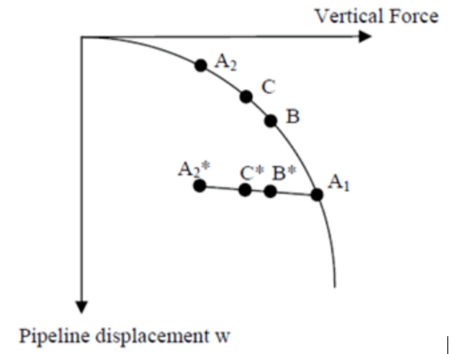
It is important to model a spring with plastic behaviour and “memory” to calculate the appropriate vertical soil stiffness. The behaviour of an over-penetrated pipe can be described by the stiff unload-reload line. When reloaded to its normally-penetrated range, the pipe’s behaviour can be described as following the virgin load embedment curve. This is illustrated in the example below and in Figure 1.
Let us first consider an elastic spring. During installation, the pipe moves to A1 due to load
concentration and then rebounds to A2, to a vertical displacement corresponding to its
submerged empty weight. During the hydrotest, the vertical force increases and the pipe
moves to B. During operational conditions, if the content is lighter than water, the pipe is
unloaded to point C. The pipe embedment and the tangent stiffness at this point are not
realistic.
In the case of an elasto-plastic spring, the pipe goes to A1 during installation and
then to A2* following an unload-reload line. During the hydrotest, the vertical force increases to B* along the unload-reload line. Finally, the pipe is unloaded to C*. At this point, the pipeline embedment and the tangent stiffness are more realistic. An accurate pipe embedment is especially important when it is coupled to axial and lateral resistance.

Coupling of axial and lateral resistance with pipeline embedment
The axial and lateral resistances depend on the contact area between the pipe and the
seabed and thus the pipe embedment, when a total stress approach is followed. The formula used to compute peak axial and lateral resistances Fpa and Fpl are in the form:

where αsu is the unit interface shear resistance, Ac is the area of contact between the pipe and the seabed which is a function of the pipe embedment z, μ is a “friction factor” in the range 0.2-0.8 (Randolph & White, 2007) and λ a coefficient typically in the range 0.5-2. The axial and lateral resistances have been linked to the pipeline embedment so that they are automatically calculated and can change during the analysis.
Tri-linear axial and lateral model
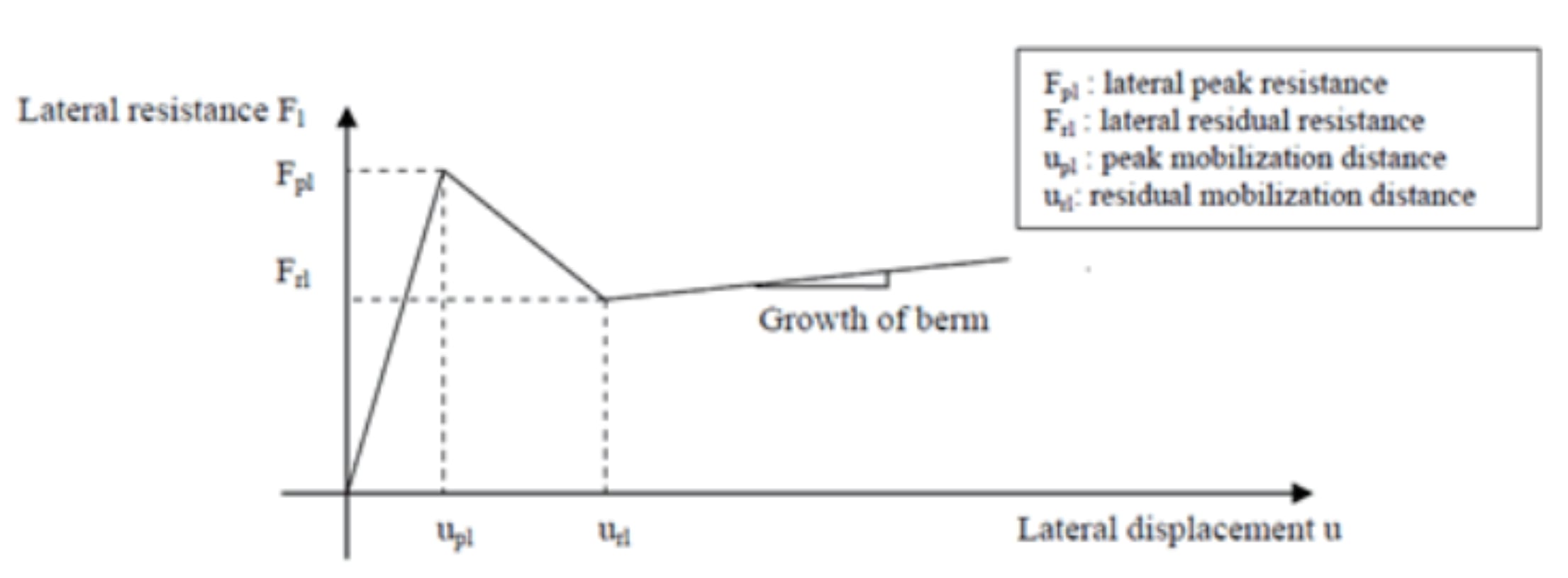
Models of the simple bi-linear frictional axial and lateral springs were improved so they can use peak and residual resistances to model the softening of the axial and lateral response often observed in clay. As explained earlier, pipelines are often over-penetrated in practice.
When this occurs in soft clay, lateral breakout resistance Fpl, is high and drops sharply when suction at the rear face of the pipe is lost, then decreases further to a residual value Frl as the pipe rises to a shallower embedment. When the residual resistance is reached, the lateral resistance may increase again because a soil berm forms in front of the pipe (see Figure 2). The axial resistance may experience strain softening as well due to suction
release and clay remoulding.

Scan4Pipes Europe GmbH
Umgehungsstraße 78b - Hauptgebäude
D-99441 Mellingen
Germany
E-Mail: office@scan4pipes.com
Phone: +49 176 346 928 81
Website: scan4pipes.com
© Scan4Pipes Europe GmbH 2019 - 2023
Steuernummer: 162/118/05297
USt.-IdNr.: DE328138499
Registergericht: Jena
Handelsregister: HRB 516297